Skip to content

904-463-3593

Serving the Southeast US


Our Services

Medium voltage engineering design services and consulting1

Medium Voltage Engineering Design Services and Consulting

Medium voltage electrical solutions ensure safety, reliability, and efficiency in electrical systems, minimizing risks and enhancing operational performance across various sectors.
Medium voltage electrical solutions refer to electrical systems and services that operate within a voltage range typically between 1 kV (1,000 volts) and 35 kV (35,000 volts). These solutions are essential for the distribution and management of electrical power in various applications, including industrial, commercial, and utility environments.

Key Components:

  • Cable Installation and Maintenance: Involves the installation, replacement, and maintenance of medium voltage cables, both underground and overhead.
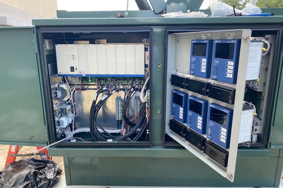
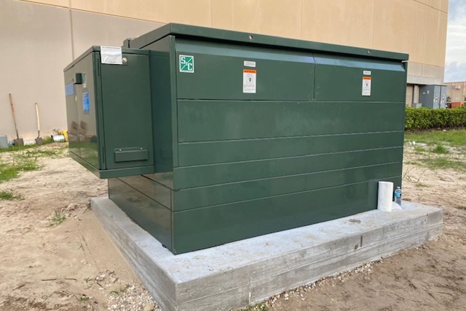
  • Transformers and Switchgear: Includes the installation and replacement of transformers and switchgear, which are critical for voltage regulation and electrical distribution.
  • Testing and Diagnostics: Encompasses testing methods such as VLF testing, partial discharge testing, and infrared thermography to ensure the reliability and safety of medium voltage systems.
  • Engineering Design and Consulting: Provides expert guidance and design services to optimize medium voltage infrastructure for specific application


Applications:

  • Power Distribution: Medium voltage solutions are crucial for distributing electricity from substations to end-users, ensuring efficient energy delivery.
  • Industrial Facilities: These solutions support machinery and equipment that require reliable power at medium voltage levels.
  • Renewable Energy: Medium voltage systems are often used in renewable energy applications, such as solar and wind, to connect generated power to the grid.
Contact Us
Control cabinet fusion power

Cable Termination and Splicing

Cable splicing is the process of joining two or more electrical cables together to extend their length or to repair a damaged cable. This is crucial in situations where a cable may be too short or has been compromised.
Cable Termination and Splicing are critical processes in the installation and maintenance of electrical cables, especially in medium voltage systems.
Cable Termination
  • Definition: Cable termination is the process of connecting the end of a cable to a device or another cable, such as a transformer, switchgear, or junction box. This connection is essential for ensuring that electrical signals can be transmitted safely and efficiently.
  • Key Aspects:
    • Preparation: Involves stripping the insulation from the cable and preparing the conductors for connection.
    • Connection: May include the use of connectors, lugs, or other hardware to secure the cable to the equipment.
    • Sealing: Often includes insulating and sealing the termination to prevent moisture ingress and enhance durability.
  • Key Aspects:
    • Types of Splicing: Can be done through various methods, including mechanical splicing and fusion splicing, depending on the cable type and application.
    • Preparation: Involves stripping the insulation from the ends of the cables to be joined.
    • Connection: Ensures a strong electrical and mechanical connection between the cables, which is essential for operational integrity.
    • Insulation: Similar to termination, splices are insulated and sealed to protect against environmental factors.

Importance

  • Safety: Proper cable termination and splicing are critical for preventing electrical faults, short circuits, and potential hazards.
  • Reliability: Ensures a continuous and stable electrical connection, which is vital for the performance of electrical systems.
  • Longevity: Well-executed terminations and splices enhance the lifespan of electrical installations by minimizing wear and environmental impact.
Contact Us
Switchgear fusion power

Transformer and Switchgear Installation and Replacement

Switchgear installation involves setting up equipment that controls, protects, and isolates electrical circuits, while replacement pertains to removing outdated or faulty switchgear and installing new units.
Transformer and switchgear installation and replacement are essential components of electrical infrastructure, particularly in medium voltage systems. Both play critical roles in the distribution and management of electrical power.

 
  • Key Aspects:
    • Installation: Includes site preparation, positioning the transformer, connecting it to power sources, and ensuring proper grounding.
    • Replacement: Involves safely disconnecting the old transformer, removing it, and installing a new unit, ensuring minimal disruption to power supply.
    • Testing: After installation or replacement, transformers undergo testing to verify operational efficiency and safety.
  • Key Aspects:
    • Installation: Includes selecting appropriate switchgear based on system requirements, installation in designated locations, and connecting it to the electrical network.
    • Replacement: Involves safely de-energizing the existing switchgear, removing it, and installing new switchgear while ensuring compliance with safety standards.
    • Testing and Commissioning: After installation, switchgear is tested to ensure proper functionality, protection, and performance specifications are met.

Importance

  • Safety: Proper installation and replacement prevent electrical hazards, ensuring safe operation of electrical systems.
  • Reliability: Ensures continuous and efficient power distribution, minimizing downtime and service interruptions.
  • Performance: Well-installed transformers and switchgear enhance the overall performance and longevity of electrical systems.
Contact Us
Cable Termination and Splicing

Medium Voltage Cable Testing

Medium voltage cable testing refers to a set of diagnostic procedures used to evaluate the integrity, performance, and safety of medium voltage cables, typically operating at voltages between 1 kV (1,000 volts) and 35 kV (35,000 volts). This testing is crucial for ensuring that the cables are in good condition and suitable for reliable electrical power distribution.
Key Testing Methods Very Low Frequency (VLF) Testing:
  • A method that applies a low-frequency voltage to the cable to detect insulation defects and other issues.
Partial Discharge Testing:
  • Measures electrical discharges that occur within the insulation of the cable, which can indicate degradation or impending failure.
Tan Delta Testing:
  • Evaluates the dielectric properties of the cable insulation, helping to identify moisture ingress and insulation deterioration.
Insulation Resistance Testing:
  • Measures the resistance of the cable insulation to direct current (DC) voltage, assessing its ability to prevent current leakage.
Time Domain Reflectometry (TDR):
  • A technique that sends a pulse down the cable to identify faults, splices, and other anomalies by analyzing reflections.
High Voltage Testing:
  • Involves applying a high voltage to the cable to ensure it can withstand operational conditions without failure.

Importance

  • Safety: Regular testing helps prevent electrical faults and hazards, ensuring the safety of personnel and equipment.
  • Reliability: Identifying issues early allows for timely repairs and minimizes the risk of unexpected failures.
  • Compliance: Ensures that cables meet industry standards and regulations, maintaining operational integrity and performance.
Medium voltage cable testing is a proactive approach to maintaining the health of electrical systems, enhancing their reliability and lifespan.
Contact Us
Transformer Testing
Transformer Testing

Transformer Testing

Transformer testing refers to a series of evaluations and diagnostic procedures performed on electrical transformers to assess their performance, efficiency, and safety. These tests are crucial for ensuring that transformers operate reliably within specified parameters and meet industry standards.
Key Testing Methods Insulation Resistance Testing:
  • Measures the resistance of insulation materials within the transformer to ensure they can effectively prevent electrical leakage.
Power Factor Testing:
  • Evaluates the efficiency of the insulation by measuring the power factor at different voltage levels, helping to identify insulation degradation.
Turns Ratio Testing:
  • Compares the primary and secondary winding voltage ratios to verify that they are consistent with the manufacturer's specifications.
Sweep Frequency Response Analysis (SFRA):
  • Analyzes the frequency response of the transformer to detect internal mechanical issues, such as winding displacements.
Load and No-Load Testing:
  • Assesses the transformer's performance under varying load conditions, measuring efficiency, voltage regulation, and temperature rise.
Thermal Imaging:
  • Uses infrared technology to identify hot spots and potential failure points by measuring surface temperatures of the transformer components.
Dissolved Gas Analysis (DGA):
  • Analyzes gases dissolved in the transformer oil to detect internal faults, such as overheating or arcing.

Importance

  • Safety: Regular testing helps prevent electrical failures, reducing the risk of accidents and enhancing operational safety.
  • Reliability: Identifying potential issues early allows for timely maintenance, ensuring continuous and efficient power delivery.
  • Longevity: Routine testing contributes to the overall health of the transformer, extending its operational lifespan and reducing maintenance costs.
Transformer testing is essential for maintaining the integrity and reliability of electrical systems, ensuring that transformers perform optimally throughout their service life.
Contact Us
Infrared/Thermography Inspection

Infrared/Thermography Inspection

Infrared/Thermography inspection is a non-destructive testing technique that uses thermal imaging technology to detect temperature variations in electrical and mechanical systems. This method is widely used in preventive maintenance to identify potential issues before they lead to failures.
Key Aspects Thermal Imaging:
  • Utilizes infrared cameras to capture images of thermal radiation emitted from objects. These images, known as thermograms, display temperature differences across the inspected surface.
Temperature Analysis:
  • The inspection process identifies hot spots, which can indicate issues such as overloaded circuits, poor connections, or failing components.
Applications:
  • Commonly used in electrical systems to inspect connections, transformers, switchgear, and circuit breakers.
  • Also applied in mechanical systems to monitor bearings, motors, and HVAC systems for signs of overheating.
Preventive Maintenance:
  • By detecting anomalies early, thermography helps prevent equipment failures, unplanned downtime, and costly repairs.
Safety:
  • Infrared inspection allows for assessments to be performed without direct contact with electrical components, enhancing safety for technicians.

Importance

  • Early Detection: Identifies potential failure points before they escalate into serious issues, allowing for timely maintenance and repairs.
  • Cost-Effective: Reduces the risk of unexpected outages and costly repairs by facilitating proactive maintenance strategies.
  • Efficiency: Quick and comprehensive evaluations of large areas and multiple components in a short time frame.
Infrared/thermography inspection is a valuable tool in maintaining the reliability and safety of electrical and mechanical systems, helping to ensure optimal performance.
Contact Us

Ready to Start?

Contact us today to discuss your project needs and
how we may be of service to you. 
Schedule a Consultation